
Diagnostic Display Quality Assurance (QA) Using a Luminance Photometer
Accurate interpretation of radiology images depends on displays that are properly calibrated and routinely verified. A medical physicist or QC technologist uses a luminance photometer (cd/m2 meter) to confirm that a diagnostic monitor meets performance targets for brightness, contrast, grayscale response, and uniformity—helping maintain consistent image presentation for radiology, mammography, and clinical review workflows.
What is being verified
Key display characteristics commonly evaluated include:
• Grayscale response (DICOM GSDF): verifies the monitor’s grayscale steps follow the DICOM Part 14 GSDF target curve (often via LUT correction).
• Luminance levels: checks Lmax (white level) and Lmin (black level) to confirm usable contrast and stable output.
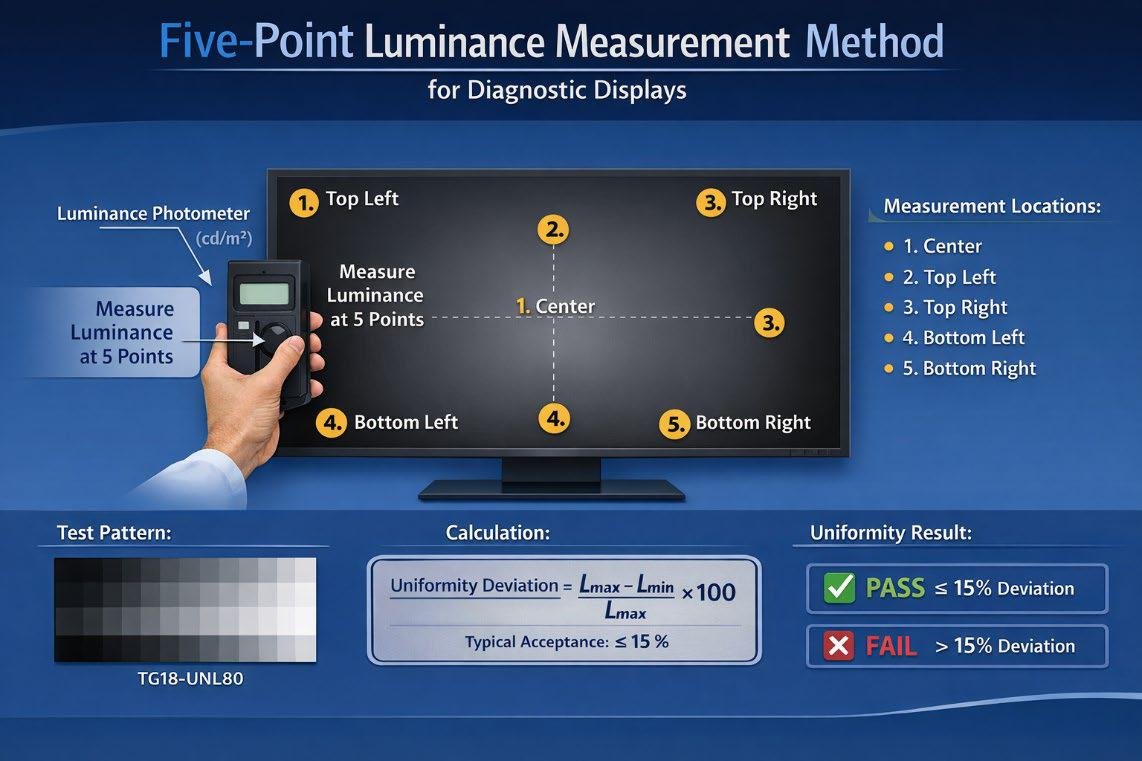
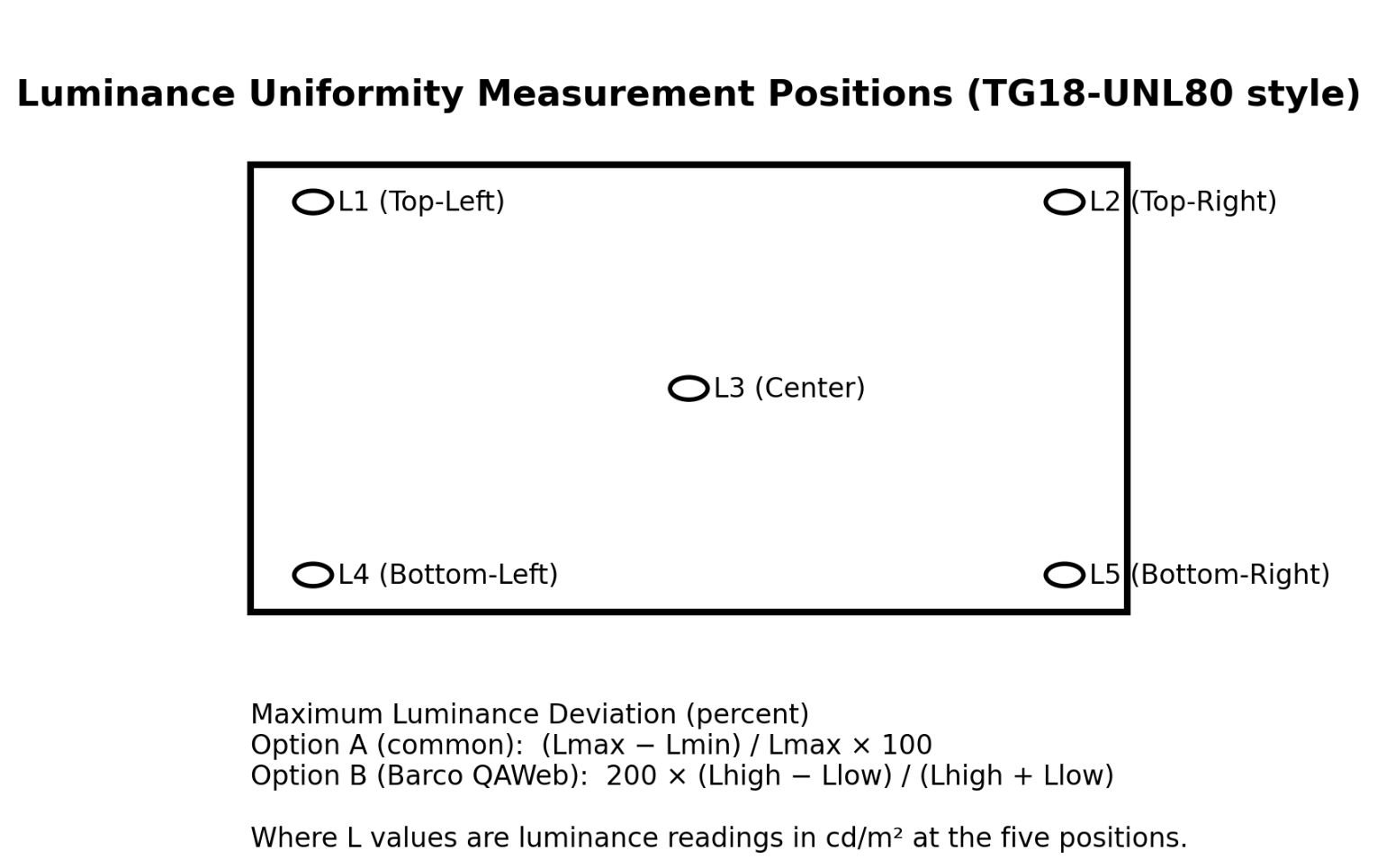
• Uniformity: confirms luminance is consistent across the screen (typically center + corners).
• Ambient light influence: controls room lighting and reflections so measurements and clinical viewing conditions remain consistent.
Tools used in the process
• Luminance photometer (cd/m2): measures light emitted by the display as perceived by the human visual system (photopic response).
• Calibration / QA software: displays standardized test patterns, records readings, and (when applicable) applies or verifies LUT calibration for GSDF compliance.
• Standard test patterns (AAPM TG18 / TG270): widely used for display acceptance testing and routine QA.
Typical step-by-step measurement workflow
Stabilize conditions: allow display warm-up and set room lighting to the facility’s normal reading-room condition; minimize glare/reflections.
Display the test pattern: commonly TG18 patterns (e.g., TG18-QC, TG18-UNL80) driven by QA software.
Measure luminance points: place the photometer perpendicular to the screen and measure center + corners to evaluate uniformity.
Verify grayscale response: measure patches (or a defined set of levels) to confirm DICOM Part 14 GSDF conformance.
Document results: save readings, calculated deviations, and pass/fail status for compliance records and trending. Document results: save readings, calculated deviations, and pass/fail status for compliance records and trending.
Ambient light control in the reading room
Ambient light can reduce perceived contrast due to reflections and viewer adaptation. Many facilities target low, stable ambient lighting in reading rooms; commonly cited ranges are around 20–40 lux (often referenced in manufacturer guidance and clinical discussions), with mammography environments frequently kept lower.
Phorad® luminance photometers support diagnostic display QC by enabling precise cd/m2 luminance measurements, repeatable uniformity checks, and documentation aligned with common QA workflows (TG18/TG270 and DICOM GSDF verification).
American Association of Physicists in Medicine (AAPM)
1. The AAPM Task Group reports are the most widely referenced documents for medical display QA.
Important Documents
• AAPM TG18 Report – Assessment of Display Performance for Medical Imaging Systems
• AAPM TG270 – QA of Medical Imaging Displays
What they include
These reports describe:
• Test patterns (TG18 patterns)
• Luminance measurement procedures
• Display uniformity tests
• Ambient light limits
• Photometer measurement techniques
• Diagnostic display calibration
Examples of TG18 patterns mentioned in your text
• TG18-UNL80 (uniformity test)
• TG18-QC (general QC pattern)
• TG18-LN (luminance response)
These are exactly the patterns used during DICOM calibration.
You can download TG18 here:
https://www.aapm.org/pubs/reports/RPT_03.pdf
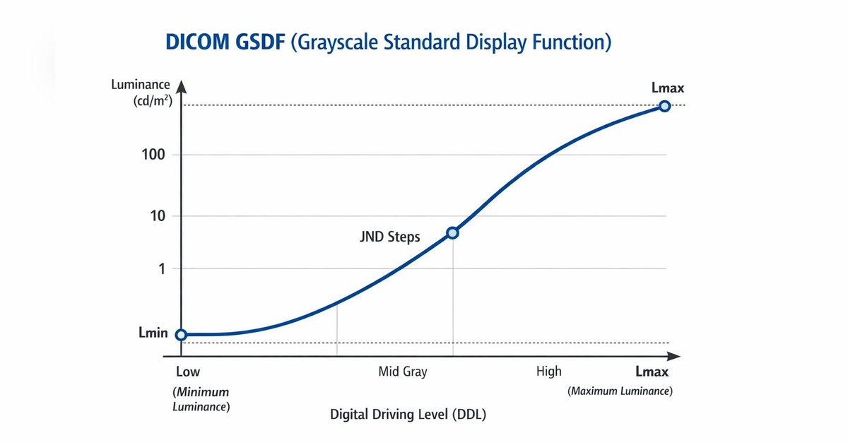
2. DICOM Part 14 Grayscale Standard Display Function
This is the core standard for medical display calibration.
DICOM Part 14 defines:
• GSDF (Grayscale Standard Display Function)
• Relationship between luminance and grayscale
• Calibration requirements
• LUT correction
GSDF ensures that:
• Every grayscale step appears perceptually linear
• Radiologists see the same contrast on different displays.
Standard reference:
https://dicom.nema.org
3. International Electrotechnical Commission
The IEC standards define international measurement methods.
Important standard:
IEC 62563-1
This standard describes:
• Measurement procedures
• Display uniformity
• Luminance measurements
• ambient light conditions
• calibration verification
This is often referenced in Barco, Eizo, and medical display manuals.
4. Manufacturer QA Systems (Practical Implementation)
Major diagnostic display manufacturers implement these standards:
• Barco
System: QAWeb
• EIZO
System: RadiCS QA
• LG Electronics
Medical display QA tools
These systems:
• show TG18 test patterns
• measure luminance with a photometer
• adjust LUT automatically
• verify DICOM compliance
5. Ambient Light Standards
Ambient lighting requirements are also documented by AAPM.
Typical values
| Environment | Recommended Ambient Light |
|---|---|
| Mammography | < 20 lux |
| Radiology reading room | 20–40 lux |
| Review workstation | up to 100 lux |
High ambient light reduces perceived contrast, which is why reading rooms are dim.
6. Measurement Instrument
The instrument used is a luminance photometer measuring:
cd/m2 (candela per square meter)
Typical measurements
• Lmax (maximum luminance)
• Lmin (black level)
• contrast ratio
• uniformity
• GSDF response
Typical acceptance criteria
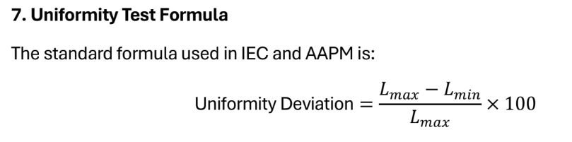
≤ 15% deviation
Measured at:
• center
• 4 corners
(5 points total)